Phone Controlled Robotic Arm
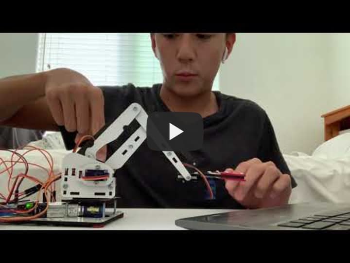
I have created a robotic arm that is controlled by a smartphone app and an ESP32 microcontroller.
| Engineer | School | Area of Interest | Grade |
|---|---|---|---|
| Michael Ding | Monta Vista High School | Computer Engineering | Incoming Senior |
Conclusion
Throughout my time at BlueStamp, I came to enjoy both the mechanical and coding aspects of the project. I found the assembling of the arm and the making of the app using MIT App Inventor to be more engaging. I also loved learning about circuits and breadboards, and getting the servo motors to move was satisfying, knowing that I wired and programmed everything correctly. The challenge that had the most profound impact on me was in the first week when my computer was not supplying enough power to keep all of the motors running. Since this was a different experience from most of the coding and debugging I have done in the past, I found that solving this problem was the most rewarding. I also realized that no matter what issue shows up, even if I have no experience with anything like it, with the right research and mentorship I will be able to solve it.
Third (Final) Milestone and Modification
My final milestone is having the mobile phone app remote control the robot arm. I connected all of the servo motors to the ESP32 and removed them from the Arduino since the ESP32 supports Bluetooth, allowing me to control the motors with my phone. While the Arduino supports Bluetooth, it requires a separate module, and the ESP32 has Bluetooth embedded within the microcontroller itself, increasing convenience without sacrificing any functionality. I then implemented my code from the first milestone, except that values are being sent from the user through Bluetooth instead of through the serial monitor.
Code:
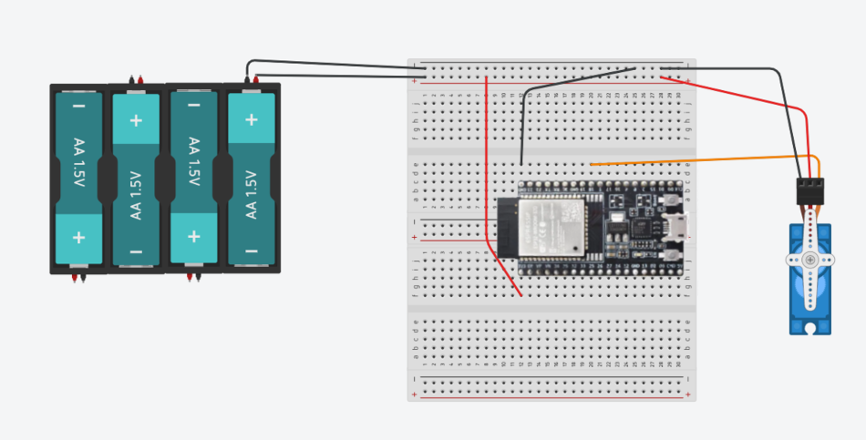
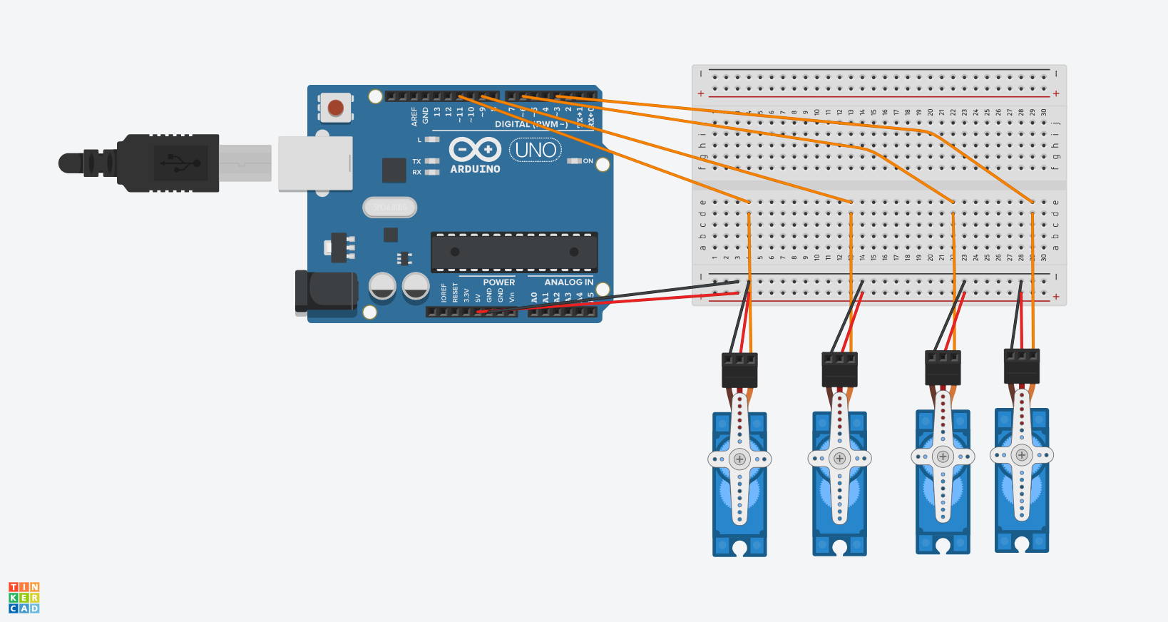
Here is a diagram of a servo motor and a 6V battery pack connected to an ESP32 with a breadboard and wires.
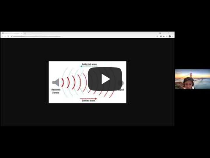
I also added an ultrasonic sensor to the robotic arm as well as functionality to have the claw close whenever an object gets within range. The ultrasonic sensor detects distances of objects by releasing sound waves and using the time between the return of the sound wave after reflection, similar to a bat. Since the speed of sound is known, the time taken for the wave to return is multiplied by the speed, which gives the total distance traveled by the wave. This distance can be divided by 2 to obtain the one-way distance, or how far the object is from the sensor. I convert this distance into inches and set the claw to clamp shut whenever the separation is less than 3 inches.
One issue I had during this milestone was that my servo motors were not turning from 0 to 180 degrees with the ESP32 connection. I found that this was due to incorrect values for two parameters for the servo attach method. The first is the pulse-width for the lowest position while the second is the pulse-width for the maximum position. Each servo motor has different values required for maximum compatibility, and with some fine-tuning, I was able to get the motors to move completely back and forth.

Second Milestone
For this milestone, I have created a mobile app using the MIT App Inventor. I also connect my smartphone with an ESP32, a controller with built-in Wi-Fi and Bluetooth capabilities. After plugging the ESP32 into my computer and setting it up with the Arduino interface, I created a program that reads input from the app on my phone through Bluetooth, creating a connection through radio waves instead of wires, which results in increased convenience.
With the new microcontroller, I downloaded a separate servo motor library in the Arduino IDE called ESP32Servo because the default Servo library is incompatible with the ESP32, and it only works when the Arduino is connected to the computer.
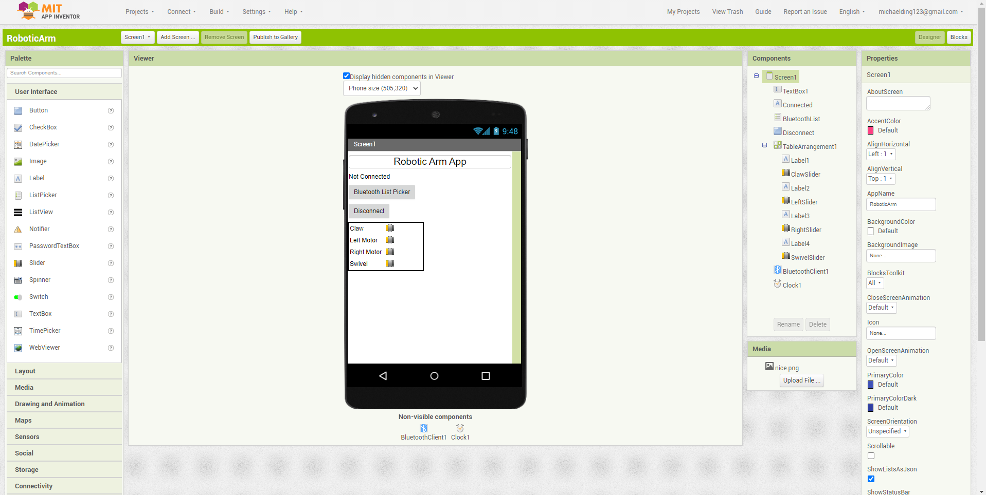
In the app inventor, I create a list picker for Bluetooth connections to choose from as well as a disconnect button. I also use a table layout where I include labels and sliders for each servo motor.
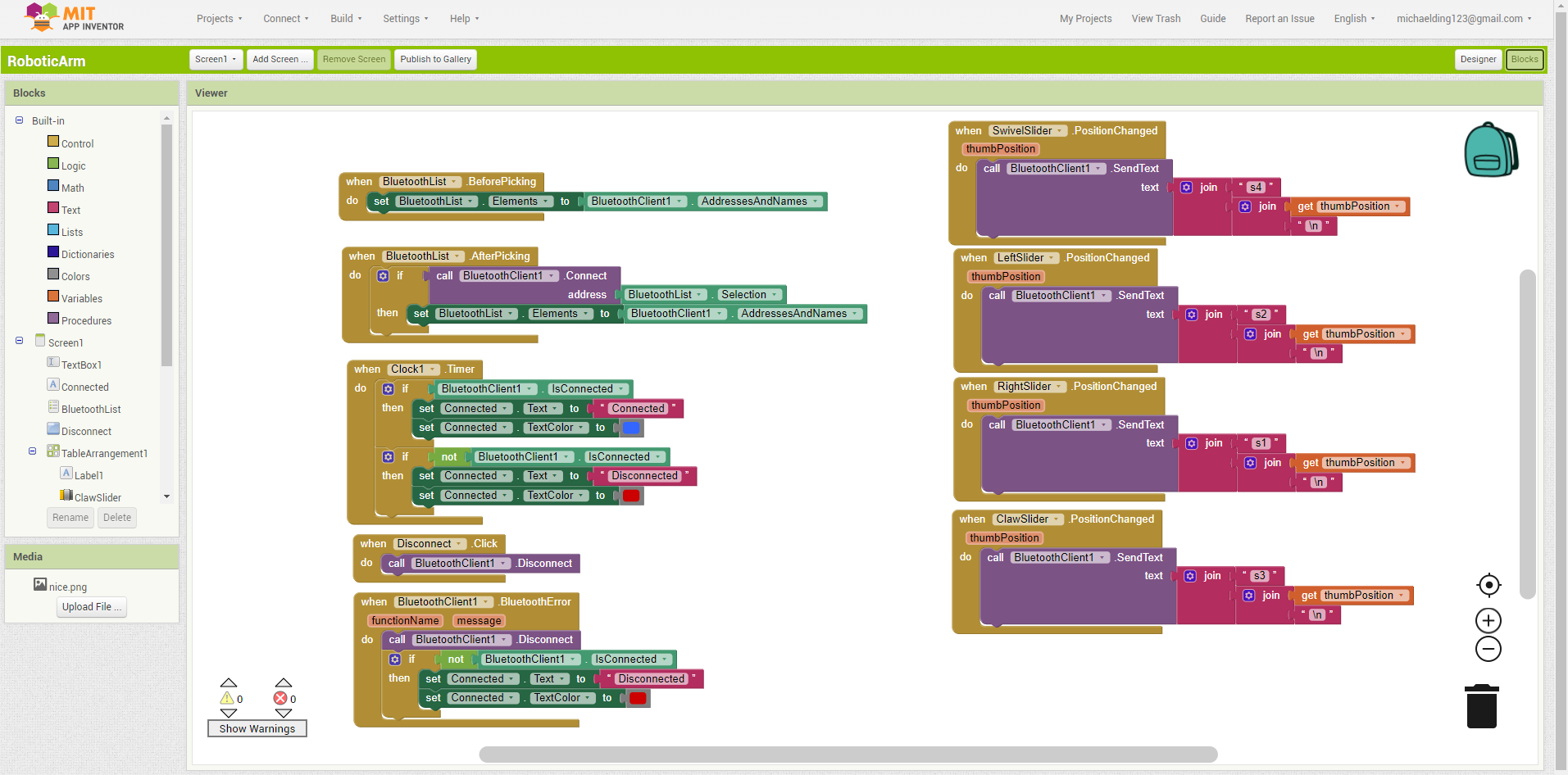
These are the code blocks for the elements inside the app. On the left are the Bluetooth controls, including functionality to change the text as well as the color when the user connects and disconnects. On the right, each slider sends the servo number (s1, s2, s3, or s4) as well as the position value between 0 and 180 degrees to the serial monitor through Bluetooth.
One issue that came up for me during this milestone was that the Arduino program implementing the ESP32 was not uploading. I eventually downloaded a separate driver for an additional COM6 port, as I figured that something was going wrong with the COM4 port that I had previously been using. After doing this, my program ran successfully.

First Milestone
My first milestone was assembling and controlling the robot arm using an Arduino. Each servo motor on the robotic arm is connected to a PWM spot on the Arduino, which allows multiple angles for my robotic arm, as well as to a power and ground spot on the breadboard. My code retrieves user input from the serial monitor, and prints it back to ensure that the text is being received. The numbers the user enters are then used to determine which servo motor to turn and which angle to turn to by using if statements. One problem I faced was that the program simply stopped running after a short amount of time. My input was not getting relayed back, and the servos were not turning. Along with this, my computer would begin to make error noises. I resolved this issue by first running the program to only turn one motor to see if there was a problem with the code or any individual servo. After determining that nothing was wrong with the code or breadboard/wire setup, I found that it was an issue of power supply. I resolved this by plugging in a 9V battery into the Arduino, which made it so the power would be supplied from an external source and not from the computer, which resolved the issue.